HEX ezCAN Tagus for Triumph Tiger 900 & Tiger 850 Sport
This is a step-by-step guide to installing the Hex ezCAN Tagus on Triumph Tiger 900 and Tiger 850 Sport models.
IMPORTANT: This installation guide is only applicable to the Triumph motorcycle models listed below. If you are installing a HEX ezCAN on a Triumph model that is not in the model list below, refer to the HEX ezCAN for Triumph Installation Guides page for guidance.
HEX ezCAN Tagus for Triumph motorcycles packaging (from April 2024 onward):
This installation guide covers the following bikes:
Tiger 900 (2020 onward)
Tiger 900 GT (2020 onward)
Tiger 900 GT Low (2020 onward)
Tiger 900 GT Pro (2020 onward)
Tiger 900 Rally (2020 onward)
Tiger 900 Rally Pro (2020 onward)
Tiger 850 Sport (2021 onward)
With OBD-II diagnostic connector or red Euro 5 diagnostic connector.
What's in the Box
HEX ezCAN installation kit contents:
1x HEX ezCAN device (Black body)
1x HEX ezCAN universal splitter cable
1x HEX OBD-II CAN-bus adapter
1x HEX JWPF-to-Euro 5 adaptor cable
1x MicroUSB-to-USB C cable with included USB C-to-USB A adaptor
4x rubber blanking seals
3x power-circuit blanking plugs
20x cable ties
4x two-wire stub connectors (Black/Orange wiring)
4x terminal wires (Orange)
ezCAN support status for Tiger 900 & Tiger 850 Sport
The CAN-bus on Tiger 900 & Tiger 850 Sport models has the following limitations:
The CAN-bus does not include ambient brightness data, meaning the motorcycle has no day/night brightness differentiation (affects some auxiliary front light functions)
The motorcycle’s Kill switch must be in the RUN position for auxiliary brake lights to work.
HEX ezCAN Tagus for Triumph motorcycles packaging (prior to April 2024):
This installation guide covers the following bikes:
Tiger 900 (2020 onward)
Tiger 900 GT (2020 onward)
Tiger 900 GT Low (2020 onward)
Tiger 900 GT Pro (2020 onward)
Tiger 900 Rally (2020 onward)
Tiger 900 Rally Pro (2020 onward)
Tiger 850 Sport (2021 onward)
With OBD-II diagnostic connector.
What's in the Box
HEX ezCAN installation kit contents (prior to April 2024):
1x ezCAN device (Silver body)
1x OBD-II CAN-bus adaptor
1x MicroUSB-to-USB A cable
2x Velcro strips
4x rubber blanking seals
2x power-circuit blanking plugs
4x cable ties
4x two-wire stub connectors (Black/Orange wiring)
4x terminal wires (Orange)
ezCAN support status for Tiger 850 & Tiger 900
The CAN-bus on Tiger 900 & Tiger 850 Sport models has the following limitations:
The CAN-bus does not include ambient brightness data, meaning the motorcycle has no day/night brightness differentiation (affects some auxiliary front light functions)
The motorcycle’s Kill switch must be in the RUN position for auxiliary brake lights to work.
Step 1: Download, Install & Configure the Software
Step 1
Download, Install & Configure the Software
This is a good time to:
Unbox the HEX ezCAN.
Decide what and how many accessories you will be installing, and their requirements. Must some accessories be connected in a specific manner and/or to specific power circuits? As an example, low-powered ‘smart’ accessories must typically be installed on the ezBUS (White) power circuit.
Read the Installing for Life section of the HEX ezCAN User Manual (downloadable from here), and evaluate your planned installation according to the guidelines in that section.
Register your HEX ezCAN (All you need to do to register the ezCAN is connect it to your computer using the supplied USB cable, meaning you can do it at the comfort of your desk.)
Step 2: Locate the Diagnostic Connector, Bluetooth Connector and Battery
Step 2
Locate the Diagnostic Connector, Bluetooth Connector and Battery
HEX ezCAN CAN-bus connection options:
Depending on year model, Triumph Tiger 900 and Tiger 850 Sport models may have more than one CAN-bus connection option:
Models with OBD-II diagnostic connector: The HEX ezCAN can be connected to the motorcycle’s:
4-pin JWPF-type Bluetooth module connector (recommended option), or
OBD-II diagnostic connector.
Models with red Euro 5 diagnostic connector: The HEX ezCAN can only be connected to the motorcycle’s red Euro 5 diagnostic connector.
Depending on year model, two different diagnostic connector types are used on HEX ezCAN Tagus-compatible Triumph Tiger 900 and Tiger 850 Sport models:
The OBD-II Diagnostic Connector
The OBD-II diagnostic connector used on earlier models looks like this:
The White 4-Pin JWPF Connector
The white 4-pin JWPF connector used on earlier models for Bluetooth connection looks like this:
The Euro 5-Type Diagnostic Connector
The Euro 5-type diagnostic connector used on later models looks like this:
Locating the diagnostic connector, Bluetooth module connector, and battery:
Remove the front and rear seats.
The diagnostic connector is located under the front seat, in the tray that holds the toolkit. An OBD-II connector is highlighted (green arrow, below).
Unscrew the white plastic nut (yellow arrow, below).
Lift the front edge of the toolkit tray, and rotate the tray toward the rear of the bike.
The battery is in the compartment under the toolkit tray.
Models with OBD-II diagnostic connector only:
The Bluetooth module connector is located on the right side of the bike, in the compartment under the toolkit tray (blue arrow).
Note: Tiger 900 and Tiger 850 Sport models with the red Euro 5 diagnostic connector do not have the Bluetooth module connector. On these models, the Bluetooth module is integrated into the instrument cluster.
Step 3: Plug the HEX ezCAN into the Bike's CAN-BUS
Step 3
Plug the HEX ezCAN into the Bike's CAN-BUS
IMPORTANT: Do not connect the HEX ezCAN’s CAN-bus connector to any part of the motorcycle other than the diagnostic connector. If you do, the ezCAN will not function.
HEX ezCAN CAN-bus connection options:
Depending on year model, Triumph Tiger 900 and Tiger 850 Sport models may have more than one CAN-bus connection option:
Models with OBD-II diagnostic connector:
We recommend connecting the HEX ezCAN to the bike’s 4-pin JWPF-type Bluetooth module connector (Option 1 below).
If connection through the Bluetooth module connector is not possible, connect the HEX ezCAN to the bike’s OBD-II diagnostic connector (Option 2 below).
Models with red Euro 5 diagnostic connector: Connect the HEX ezCAN to the bike’s red Euro 5 diagnostic connector (Option 3 below).
If the motorcycle is equipped with an OBD-II diagnostic connector, the motorcycle’s 4-pin male JWPF connector will be in one of two configurations:
If your motorcycle has the optional Bluetooth module: The 4-pin male JWPF connector on the motorcycle’s wiring harness will be plugged into the Bluetooth module.
If your motorcycle does not have the optional Bluetooth module: The 4-pin male JWPF connector on the motorcycle’s wiring harness will be covered by a protective cover.
Tips:
To separate male and female JWPF connectors that are joined, gently press down the locking tab on the female connector with the blade of a small flat screwdriver while pulling the connectors apart. Do not pull on the wiring.
If the locking mechanism of any JWPF connector is damaged, the male and female connectors can easily be re-secured by sliding a piece of Nylon heat-shrink tubing over the connectors and heat-shrinking the tubing in place. Alternatively, use electrical insulation tape.
Option 1
Connecting the HEX ezCAN to the Bluetooth module connector
Install and connect the HEX ezCAN by doing the steps that follow:
Install the main body of the HEX ezCAN in the battery compartment under the toolkit tray.
Connect the 4-pin male JWPF connector on the ezCAN to either of the 4-pin female JWPF connectors on the HEX ezCAN universal splitter cable.
Connect the remaining 4-pin female JWPF connector on the HEX ezCAN universal splitter cable to the bike’s Bluetooth module (upper left arrow, below).
Connect the 4-pin male JWPF connector on the HEX ezCAN universal splitter cable to the bike’s female JWPF wiring harness connector (below).
Option 2
Connecting the HEX ezCAN to an OBD-II Diagnostic Connector
IMPORTANT: OBD-II connectors have no locking mechanism. If the bike has an OBD-II diagnostic connector, make sure the HEX ezCAN adaptor’s male OBD-II connector cannot accidentally separate from the bike’s OBD-II diagnostic connector. We recommend that you secure the join between the male and female OBD-II connectors with self-sealing tape or electrical insulation tape.
Install and connect the HEX ezCAN by doing the steps that follow:
Install the main body of the HEX ezCAN in or near the toolkit tray, or in the battery compartment under the toolkit tray.
Connect the JWPF-to-OBD-II adaptor cable in the HEX ezCAN kit to the 4-pin male JWPF connector on the ezCAN.
Connect the male OBD-II connector of the JWPF-to-OBD-II adaptor cable to the bike’s OBD-II diagnostic connector.
Option 3
Connecting the HEX ezCAN to a Euro 5 Diagnostic Connector
Install and connect the HEX ezCAN by doing the steps that follow:
Install the main body of the HEX ezCAN in or near the toolkit tray, or in the battery compartment under the toolkit tray.
Connect the JWPF-to-Euro 5 adaptor cable in the HEX ezCAN kit to the 4-pin male JWPF connector on the ezCAN.
Connect the male Euro 5 connector of the JWPF-to-Euro 5 adaptor cable to the bike’s diagnostic connector.
Step 4: Connect the HEX ezCAN to the Bike's Battery
Step 4
Connect the HEX ezCAN to the Bike's Battery
Route both HEX ezCAN power supply cables from the main body location to the battery.
Ensure that all wiring is routed safely and securely, in a way that does not allow it to chafe or pinch. Where needed, secure all wiring to frame tubes or other components using the cable ties supplied with the HEX ezCAN installation kit.
WARNING: For safety reasons, always disconnect the negative battery terminal first, and re-connect it last.
Disconnect the negative wiring harness terminal from the negative battery pole.
Disconnect the positive wiring harness terminal from the positive battery pole.
Connect the terminal on the orange ezCAN power cable, and the bike’s positive wiring harness terminal, to the positive battery pole.
Connect the terminal on the brown ezCAN power cable, and the bike’s negative wiring harness terminal, to the negative battery pole.
Re-install the battery cover.
Tidy the CAN-bus and battery cable routing, making sure you have easy access to the four power circuit plugs.
Secure all loose cables using the cable ties included in the HEX ezCAN installation kit.
Note: The HEX ezCAN’s status LED should be solid green for approximately a minute after connection to the battery. After this time, the ezCAN enters Sleep Mode, and there will be no LED activity until the bike’s ignition is switched ON.
Step 5: Connect the Accessories, using Colour Coding
Step 5
Connect the Accessories, using Colour Coding
The HEX ezCAN installation kit includes four two-wire stub connectors with male connection terminals, orange power wires and black ground wires.
The following parts are also included:
4x pulse-width modulation (PWM) terminal wires (orange with white tracer)
4x rubber blanking seals
If the accessory to be connected to a power circuit has three wires, convert a two-wire stub connector to a three-wire connector as shown in the Connecting 3-wire LED lights section of the HEX ezCAN User Manual (downloadable from here).
If the accessory to be connected to a power circuit has two wires, seal the stub connector’s empty terminal cavity as shown in the Connecting 2-wire accessories section of the HEX ezCAN User Manual.
If any of the HEX ezCAN’s power circuits will not be used, we recommend that you connect a blanking plug to the output plug of each unused circuit.
Play Video
2-wire applications: insert a blanking seal. 3-wire applications: insert a PWM terminal wire.
4 x Terminal wires and Blanking seals
4 x Two Wire Stub Connectors
Connect the male terminal of each stub connector to the relevant female HEX ezCAN power circuit connector (below).
Connecting a 2-wire accessory to a HEX ezCAN stub connector:
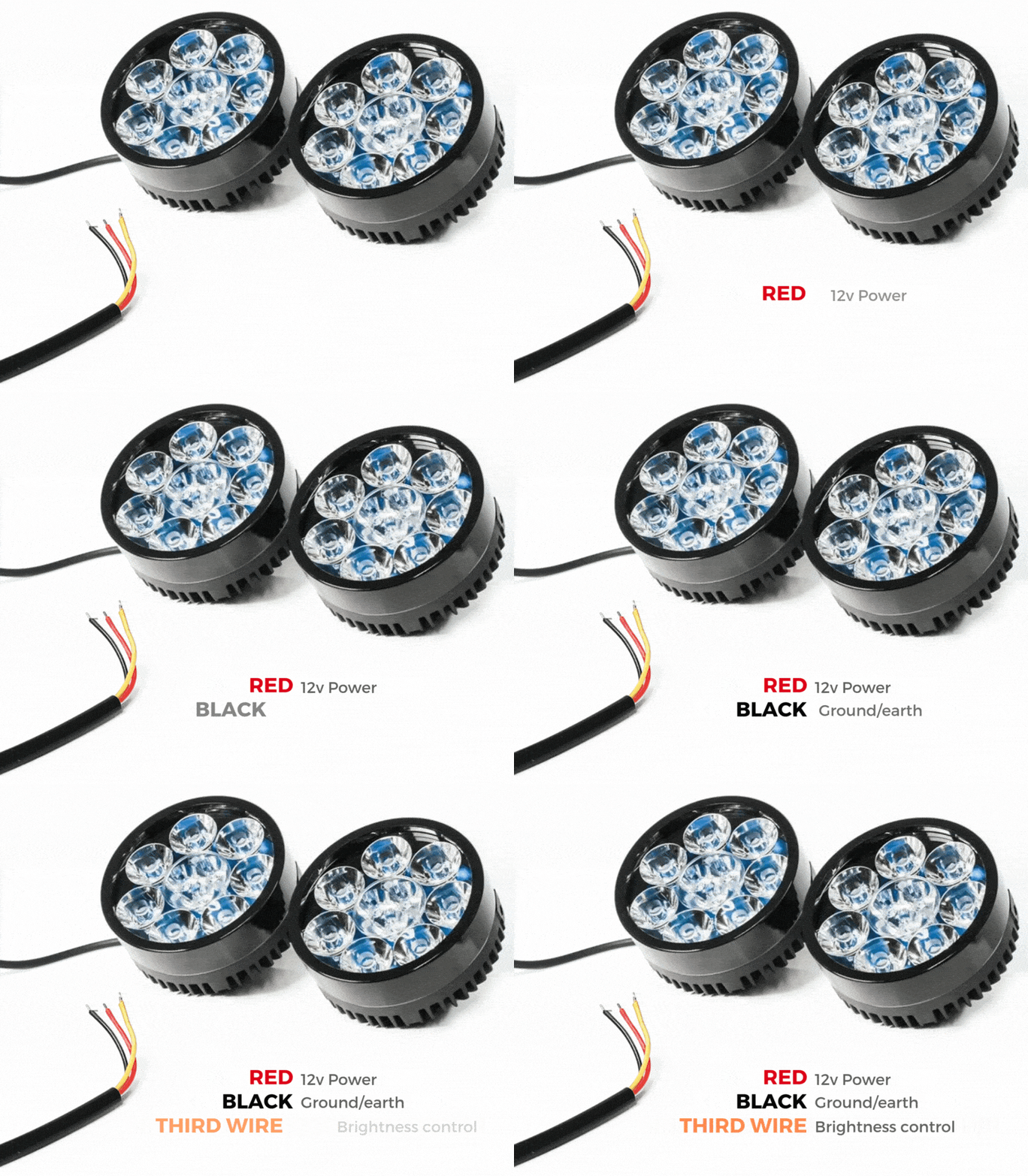
Connect the accessory’s ground/Earth wire (this is usually, but not always black or brown) to the ground wire of a HEX ezCAN stub connector.
Connect the accessory’s power wire (this is usually, but not always red) to the 12V power wire of a HEX ezCAN stub connector.
Connecting a 3-wire accessory to a HEX ezCAN stub connector:
Connect the accessory’s ground/Earth wire and power wire as described above.
Connect the accessory’s PWM control wire to the dual-colour (solid colour+tracer) wire of an ezCAN stub connector.
Connecting low-power smart accessories to a HEX ezCAN stub connector:
Read the HEX ezBUS and Configuring HEX ezBUS functionality sections of the HEX ezCAN user manual (downloadable from here) for detailed information on how to use ezBUS functionality.
If you are installing ‘smart’ accessories (that is, low-power accessories capable of intelligent input and control through the HEX ezCAN’s LIN bus), note the following:
Smart accessories (including the HEX ezSWITCH) must only be connected to the HEX ezCAN’s ezBUS (white) power circuit. Smart accessories will not work if connected to the red, yellow or blue circuits.
The ezBUS (white) power circuit can accommodate any odd or even number of individual accessories, to a maximum of fifteen.
A selection of HEX ezBUS adaptors and connectors is available, allowing you to connect smart accessories quickly and easily. See the ezBUS Accessories section of the HEX Innovate online store for details.
Read the HEX ezBUS and Configuring HEX ezBUS functionality sections of the HEX ezCAN user manual (downloadable from here) for detailed information on how to use ezBUS functionality.
Note that if the white circuit is set to ezBUS mode, its fuse trip limit is set to 15 Amps by default. If needed, ezBUS PWR functionality can be used to increase the white circuit’s current capacity to a maximum of 30 Amps in ezBUS mode. See the relevant section of the HEX ezCAN User Manual for details.
IMPORTANT: If the stub connectors included in your HEX ezCAN installation kit do not have orange power wires, but instead have colours that match the colouring of the HEX ezCAN power circuits (as seen below), always connect like-to-like (red stub connector to red power circuit, blue stub connector to blue power circuit, and so on.)
Easier Installation with the HEX ezCAN Extension Kit
The HEX ezCAN Extension Kit contains everything you need to connect front auxiliary lights, rear accessory lights and a horn to the HEX ezCAN. It also includes additional connectors that allow you to connect other accessories.
2x 1.5m 3-core extension cables (typically used for 2-wire or 3-wire front auxiliary lights)
1x 0.5m 3-core extension cable (typically used for a rear running/brake light)
1x 1.5m 2-core extension cable, with spade connectors (typically used to connect air horns or other 2-wire accessories)
3x female MT-3 connectors, including terminal pins and terminal seals
5x male MT-3 connector kit, including terminal pins and terminal seals
5x rubber blanking seals (used in cases where only two terminals are used in a 3-wire MT-3 connector)
6x 20mm sections of adhesive-lined heat-shrink tubing
2x 6.3mm female spade connector terminals
1m cable sheathing
Adhesive lined heat shrink & 1m sheathing
Front auxiliary lights extensions
Horn extension
Brake/Accessory extension
Step 6: Test the Installation
Step 6
Test the Installation
WARNING: Test and check your installations and accessories in a safe, controlled environment before first use. Caution is advised at all times. Extra vigilance is needed when testing new features or accessories. You do so at your own risk.
DISCLAIMER: HEX Innovate is not liable for any injury or damage, howsoever caused, and all products and services are used at your own risk.
Before finalizing the HEX ezCAN installation or re-installing any components you may have removed, it is important that you test all newly installed accessories for satisfactory fitment and correct operation.
Many HEX ezCAN-powered accessories can be tested by switching the ignition ON and operating the relevant controls. Exceptions include:
Accessories for which you have enabled the Only on when engine running feature (examples may include Aux 1 lights, Aux 2 lights, MotoLights, and heated clothing). To test these functions, the bike’s engine must be running.
Some brake light functions require that the bike be moving at or above a certain speed. As examples, Flash on Emergency Stop and Flash on Rapid Engine Braking functions require deceleration of more than 21 Kilometres per hour per second.
Step 7: Complete the Installation
Step 7
Complete the Installation
Complete the HEX ezCAN installation as follows:
Make sure the main body of the HEX ezCAN is well-secured in a place where it is protected from pressure, heat and impact.
Make sure all factory, ezCAN and accessory cables and wiring harnesses are well clear of all moving parts, and securely fastened. Where needed, use the cable ties included in the HEX ezCAN installation kit.
Replace all motorcycle components and fasteners that may have been removed to facilitate the ezCAN installation.
Inspect the complete installation for mistakes or problems, and fix all problems that you have noted.
Test all new accessories for correct operation a second time.
If you have not already done so, download the HEX ezCAN user manual from this page. Keep the manual in a safe place on your computer, tablet or phone: it contains all the information you need to operate the HEX ezCAN and adjust its functionality.
Please note !
You will now be redirected to our primary website to view our Privacy Policy
We use cookies to ensure that we give you the best experience on our website. If you continue to use this site we will assume that you are happy with it.