This is a step-by-step guide to installing the HEX ezCAN Ordos for KTM.
IMPORTANT: This installation guide is only applicable to the KTM motorcycle models listed below. If you are purchasing a HEX ezCAN for, or installing a HEX ezCAN on a KTM that is not in the model list below, refer to the HEX ezCAN Gobi for KTM Bikes to see if this acceesry manager supports your KTM. If not, the HEX ezCAN PURE Universal Accessory Manager supports pretty much any 12V motorcycle, including models that do not have a CAN-bus system.
HEX ezCAN Ordos for KTM motorcycles packaging:
The following bikes are supported:
1390 Super Adventure S (2026+)
1390 Super Adventure S EVO (2026+)
1390 Super Adventure R (2026+)
What's in the Box
1x HEX ezCAN Ordos device (Black body)
1x Micro USB to USB A and C cable
4x 2-wire stub connectors (Black/Orange wiring)
4x 1-wire terminal wires (Orange)
4x blanking seals
3x blanking Plugs
20x cable Ties
Step 1: Download, Install & Configure the Software
Step 1
Download, Install & Configure the Software
Getting Started: Initial Setup Checklist
Before you begin the physical installation, complete these quick preparation steps:
Unbox your HEX ezCAN and check that all components are present.
Plan your accessories: Decide which devices you want to install and check their power requirements.
Note: Pay attention to specific circuit requirements. For instance, ‘smart’ Certified ezBUS-Ready accessories need to be wired into the ezBUS (White) power circuit.
Review the manual: Read the Installing for Life section in the HEX ezCAN User Manual (available to download from the website) to make sure your planned setup meets the recommended guidelines.
Register your device: Simply connect the HEX ezCAN to your computer using the provided USB cable. You can easily complete this step from the comfort of your desk before heading out to the bike.
Step 2: Locate the Battery and OBD-II Diagnostics Connector
Step 2
Locate the Battery and OBD-II Diagnostics Connector
Needed tools:
10mm wrench or socket to connect the HEX ezCAN to the battery terminals
Access the vehicle battery and OBD-II connector as follows:
Remove the rider and pillion seats.
If your bike has heated seats, unplug the seat-heating connectors under the rider and pillion seats.
Locate the bike’s battery terminals (See below left).
Cable Routing: The HEX ezCAN battery terminal cables can be routed underneath the sub-frame cross-brace, from the space underneath the pillion seat.
The HEX ezCAN Ordos connects to the KTM CAN-bus via the OBD-II Diagnostics Terminal (below, right).
Location of the Battery Terminals
Location of OBD-II Diagnostics Terminal
Step 3: Plug the HEX ezCAN into the Bike's CAN-BUS
Step 3
Plug the HEX ezCAN into the Bike's CAN-BUS
Remove dust cover from the OBD-II terminal.
Connect the HEX ezCAN Ordos CAN-Bus connector to the OBD-II terminal.
Make sure that the connection is inserted straight and firmly pushed into the terminal.
Remove the dust cover from the OBD-II terminal.
Step 4: Connect the HEX ezCAN to the Bike's Battery
Step 4
Connect the HEX ezCAN to the Bike's Battery
The best location for the main body of the HEX ezCAN device is underneath the pillion seat.
When planning your accessory cables, ensure that the wiring is routed safely and securely, in a way that does not allow it to chafe or pinch. Where needed, secure all wiring to frame tubes or other components using the cable ties supplied with the HEX ezCAN installation kit.
WARNING: For safety reasons, always disconnect the negative battery terminal first, and re-connect it last.
Start the installation by locating the main body of the HEX ezCAN in a place that allows straightforward, logical wiring runs. We recommend installing the HEX ezCAN main body underneath the pillion seat area, as this allows easier access for firmware updates and diagnostics.
Route the HEX ezCAN battery terminal connection underneath the sub-frame cross-brace.
Disconnect the negative wiring harness terminal from the negative battery pole.
Disconnect the positive wiring harness terminal from the positive battery pole.
Connect the terminal on the orange ezCAN power cable, and the bike’s positive wiring harness terminal, to the positive battery pole.
Connect the terminal on the brown ezCAN power cable, and the bike’s negative wiring harness terminal, to the negative battery pole.
Tidy the CAN-bus and battery cable routing. Secure all loose cables using the cable ties included in the HEX ezCAN installation kit.
Note: The HEX ezCAN’s status LED should be solid green for approximately a minute after connection to the battery. After this time, the HEX ezCAN enters Sleep Mode, and there will be no LED activity until the bike’s ignition is switched ON.
Connect the HEX ezCAN to the positive battery terminal, then to the negative battery terminal. Tidy and secure the cables. Make sure you have easy access to the four power circuit plugs.
Step 5: Connect the Accessories, using Colour Coding
Step 5
Connect the Accessories, using Colour Coding
The HEX ezCAN installation kit includes four two-wire stub connectors with male connection terminals, orange power wires and black ground wires.
The following parts are also included:
4x pulse-width modulation (PWM) terminal wires (orange with white tracer)
4x rubber blanking seals
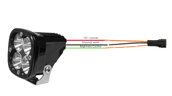
If the accessory to be connected to a power circuit has three wires, convert a two-wire stub connector to a three-wire connector as shown in the Connecting 3-wire LED lights section of the HEX ezCAN User Manual (downloadable from here).
If the accessory to be connected to a power circuit has two wires, seal the stub connector’s empty terminal cavity as shown in the Connecting 2-wire accessories section of the HEX ezCAN User Manual.
If any of the HEX ezCAN’s power circuits will not be used, we recommend that you connect a blanking plug to the output plug of each unused circuit.
2-wire applications: insert a blanking seal. 3-wire applications: insert a PWM terminal wire.
4 x Terminal wires and Blanking seals
4 x Two Wire Stub Connectors
Connect the male terminal of each stub connector to the relevant female HEX ezCAN power circuit connector (below).
Connecting a 2-wire accessory to a HEX ezCAN stub connector:
Connect the accessory’s ground/Earth wire (this is usually, but not always black or brown) to the ground wire of a HEX ezCAN stub connector.
Connect the accessory’s power wire (this is usually, but not always red) to the 12V power wire of a HEX ezCAN stub connector.
Connecting a 3-wire accessory to a HEX ezCAN stub connector:
Connect the accessory’s ground/Earth wire and power wire as described above.
Connect the accessory’s PWM control wire to the dual-colour (solid colour+tracer) wire of an ezCAN stub connector.
Connecting ‘smart’ Certified ezBUS-Ready accessories to a HEX ezCAN stub connector:
Read the HEX ezBUS and Configuring HEX ezBUS functionality sections of the HEX ezCAN user manual (downloadable from here) for detailed information on how to use ezBUS functionality.
If you are installing ‘smart’ Certified ezBUS-Ready accessories (that is, accessories capable of intelligent input and control through the HEX ezCAN’s LIN bus), note the following:
Smart accessories (including the HEX ezSWITCH) must only be connected to the HEX ezCAN’s ezBUS (white) power circuit. Smart accessories will not work if connected to the red, yellow or blue circuits.
The ezBUS (white) power circuit can accommodate upto a maximum of fifteen Certified ezBUS-Ready accessories.
A selection of HEX ezBUS adaptors and connectors is available, allowing you to connect smart accessories quickly and easily. See the ezBUS Accessories section of the HEX Innovate online store for details.
Read the HEX ezBUS and Configuring HEX ezBUS functionality sections of the HEX ezCAN user manual (downloadable from here) for detailed information on how to use ezBUS functionality.
Note that if the white circuit is set to ezBUS mode, its fuse trip limit is set to 15 Amps by default. If needed, ezBUS PWR functionality can be used to increase the white circuit’s current capacity to a suggested maximum of 25 Amps in ezBUS mode. See the relevant section of the HEX ezCAN User Manual for details.
IMPORTANT:
The four output circuits on your ezCAN are colour-coded. When you plug in an accessory—like auxiliary lights, a horn, or a brake light—just take note of the wire colour for that specific circuit.
When you open the HEX ezCAN software, you’ll see those exact same colours listed under the Circuit Functions section. Simply match the software configuration to the wire colour you connected your accessory to, and you’re good to go!
Plug it in: Connect your accessory to a colour-coded circuit output.
Match it up: Open the ezCAN software and select the matching colour to assign its function.
Easier Installation with the HEX ezCAN Accessories
Whether you’re fitting front spot lights, a extra rear brake light, a loud air horn, or your favourite heated kit, HEX ezCAN has you covered.
We offer a complete range of cables, adaptors, splitters, and connectors to help you wire up virtually any combination of electronic gear to your ezCAN—plus plenty of spare connectors to keep in your toolkit for future builds.
Click the links below to explore the full range of accessories:
WARNING: Test and check your installations and accessories in a safe, controlled environment before first use. Caution is advised at all times. Extra vigilance is needed when testing new features or accessories. You do so at your own risk.
DISCLAIMER: HEX Innovate is not liable for any injury or damage, howsoever caused, and all products and services are used at your own risk.
Before finalizing the HEX ezCAN installation or re-installing any components you may have removed, it is important that you test all newly installed accessories for satisfactory fitment and correct operation.
Many HEX ezCAN-powered accessories can be tested by switching the ignition ON and operating the relevant controls. Exceptions include:
Accessories for which you have enabled the Only on when engine running feature (examples may include Aux 1 lights, Aux 2 lights, MotoLights, and heated clothing). To test these functions, the bike’s engine must be running.
Some brake light functions require that the bike be moving at or above a certain speed. As examples, Flash on Emergency Stop and Flash on Rapid Engine Braking functions require deceleration of more than 21 Kilometres per hour per second.
Step 7: Complete the Installation
Step 7
Complete the Installation
Complete the HEX ezCAN installation as follows:
Make sure the main body of the HEX ezCAN is well-secured in a place where it is protected from pressure, heat and impact.
Make sure all factory, ezCAN and accessory cables and wiring harnesses are well clear of all moving parts, and securely fastened. Where needed, use the cable ties included in the HEX ezCAN installation kit.
Replace all motorcycle components and fasteners that may have been removed to facilitate the ezCAN installation.
Inspect the complete installation for mistakes or problems, and fix all problems that you have noted.
Test all new accessories for correct operation a second time.
If you have not already done so, download the HEX ezCAN user manual from this page. Keep the manual in a safe place on your computer, tablet or phone: it contains all the information you need to operate the HEX ezCAN and adjust its functionality.
Please note !
You will now be redirected to our primary website to view our Privacy Policy
We use cookies to ensure that we give you the best experience on our website. If you continue to use this site we will assume that you are happy with it.